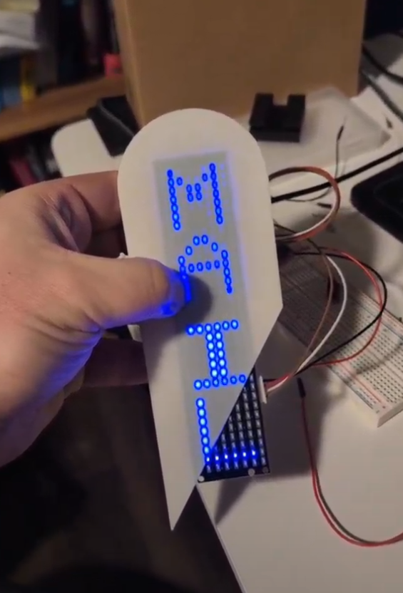
What started out as a dedicated piece of hardware for a driveway and mailbox sensor has since turned into a quick message board for me to pass love notes to my wife during the day.
Demo Video
Backstory
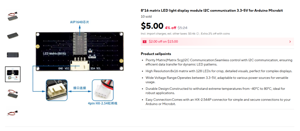
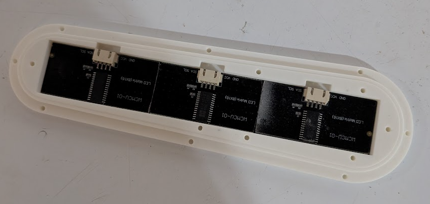
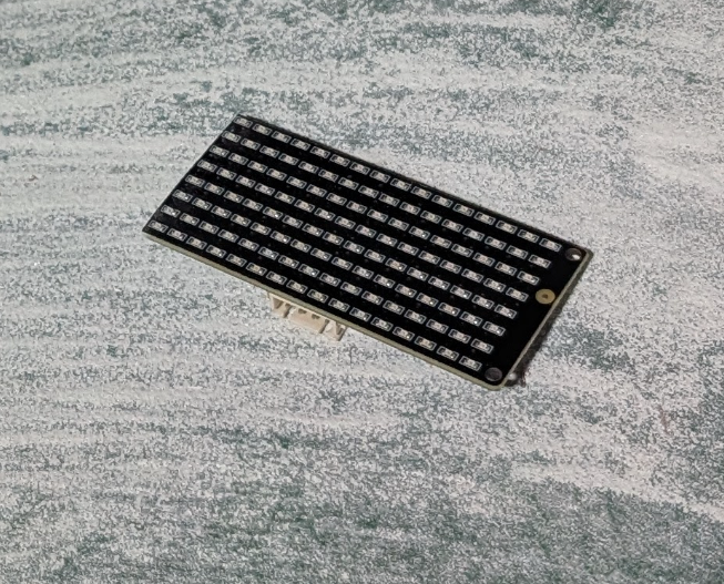
A few years ago I purchased a set of 4x of these 8×16 LED displays after watching a video by Upir.
I was inspired to make a binary clock with a custom aperture made on my bambulab printer (super exciting, this multiple-filament business). It was a fun start and honestly a good excuse to vibe code up some real-world displays. I wanted a desktop toy that I could power with an ESP32 and display the time, weather, and some other data.
This was shortly before I decided on the CRT Weather Display as my primary project for 2025. These LED panels quickly got shelved.
Fast forward to 2025 and my wife and I had a second kid, bought a house, and are now dealing with a long walk to the mailbox and no way to tell if someone is coming up our driveway.
Like Chekhov’s Gun these little panels sat in my box full of random project parts for a little over two years only to meet their fate last night.
Beginning
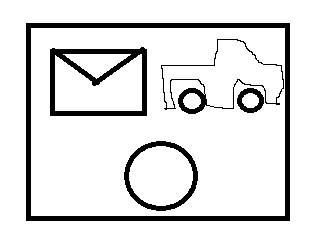
The idea came to me as I was exploring options for notifying the household of mail or a vehicle coming up my driveway. Why not have a dedicated art piece that contains a bell, and a set of icons for discerning between us getting mail and a car driving up the road? Light up the mail icon for mail and the truck icon for road. This would let me use those panels I bought so long ago (and make custom light masks on my 3D printer again!) I’m losing money if I don’t buy the bell for this project!
I got the bell on order from AliExpress as the Amazon options were quite limited and honestly too large for my need. I would have chosen a smaller bell, but lacked the search terms to find something smaller and cheaper. In hindsight an unpowered children’s bicycle bell would have probably worked just fine!
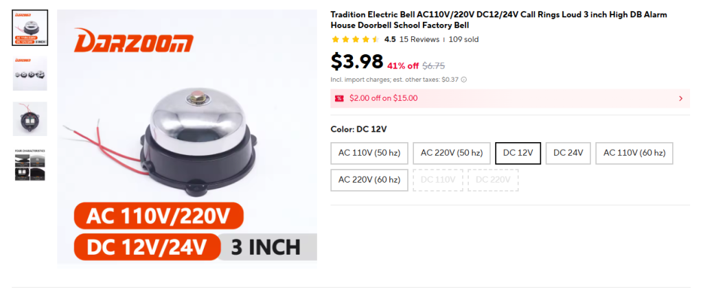
Once the bell arrived I tested it out and it quickly found a spot on my shelf next to all the other project parts I’ll definitely get to some day. I didn’t quite like the way it clanged like a fire alarm so I needed to brainstorm solutions for that.
The bell then sat dormant for the next four months.
I’m on a Roll!
Since it’s winter, a lot of my outdoor home improvement tasks have been put on hold while I wait out the rain here in the Pacific Northwest. I had a few mission critical tasks I needed to sort out before I could get to the notifier however. Through some miracle, my 5 backburner projects have all been completed or in a state where I was out of excuses for not working on this one.
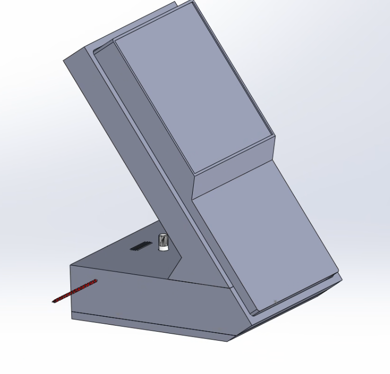
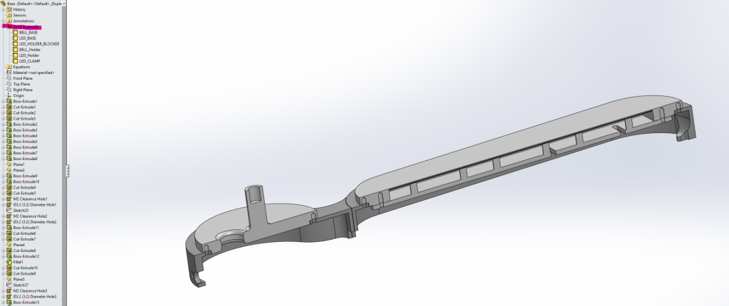
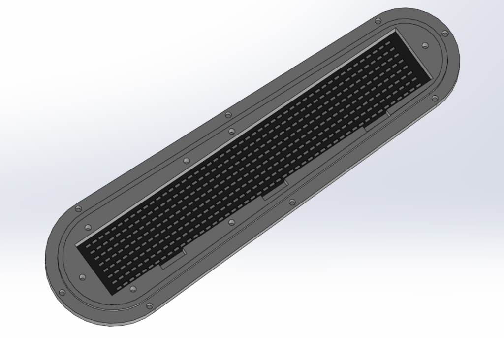
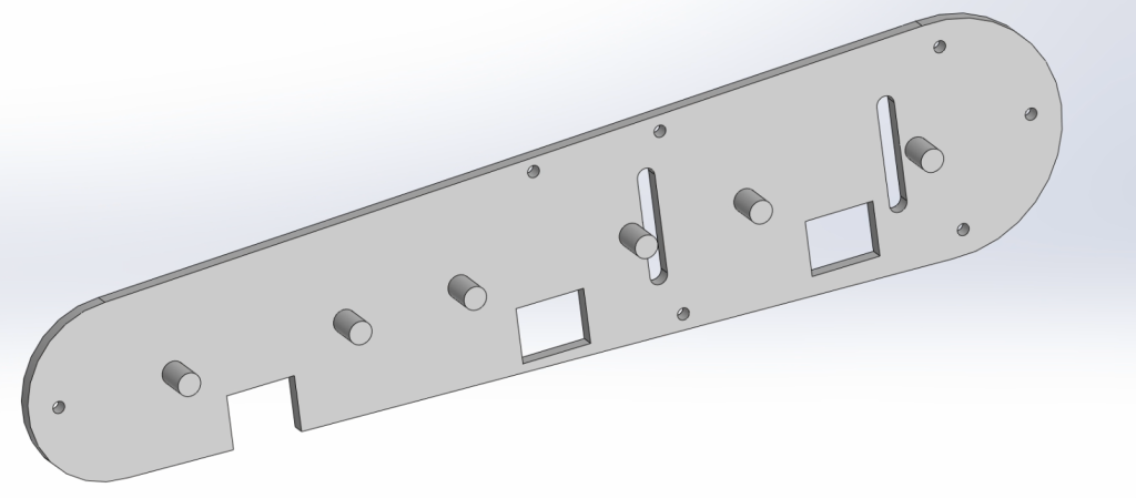
With the long President’s day weekend ahead of me I began drafting my idea in Solidworks. I designed a simple, bi-color proof of concept unit that I could hang on a wall and test fit around the house.
The first problem this design highlighted was how freaking large it was! I could not get the whole thing to fit on the bed of my printer so I had to cut it into pieces and glue them together later.

Quick Side Bar
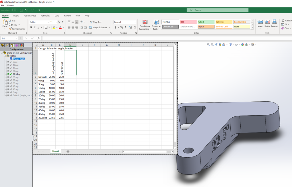
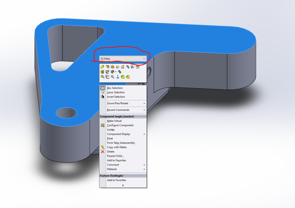
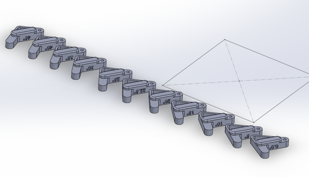
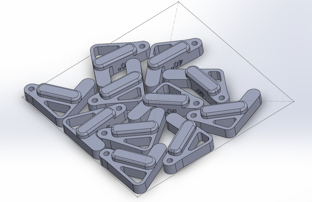
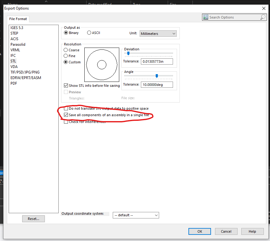
In order to cut the model into pieces I used the Split command in solidworks. This turned my singular part into multiple bodies. To make 3D printing easier (one filament per body) I also unchecked “Merge result” in my boss extrudes. I was then left with four bodies to export as STEP files. To do this manually (at least in SW2014) is SUPER TEDIOUS. The user has to delete the unused bodies, save the single body as a STEP, undo the delete, and re-delete a new set of bodies for the next save. This quickly got old so I turned to the internet plagiarism machine to help me write my first macro. With a little debugging I actually got functional code and a macro that exports all bodies in a part within seconds! I also stole/made a macro for multi-body STL files, but don’t like how STL handles curves. Both macros are posted below. The STL macro is tailored to put the output files into C:\Users\solidworks\Desktop\Conrads Projects\Multi_Body_STL_Exports be sure to change this for your setup!
MULTI-BODY STEP EXPORTER MACRO
Option Explicit

' --- numeric constants ---
Const swDocPART = 1
Const swExportSTEP = 6
Const swSaveAsCurrentVersion = 0
Const swSaveAsOptions_Silent = 2
Const swSaveAsOptions_Copy = 8
Const TEMPLATE_PATH = "C:\ProgramData\SolidWorks\SolidWorks 2014\templates\Part.prtdot"


Dim swApp As Object
Dim src As Object               ' ModelDoc2 (source part)
Dim BodyArr As Variant

Sub main()
    Set swApp = Application.SldWorks
    Set src = swApp.ActiveDoc
    If src Is Nothing Then Exit Sub
    If src.GetType <> swDocPART Then
        MsgBox "Open a PART document.", vbExclamation
        Exit Sub
    End If
    ' If the part isn't saved, we'll export to Desktop
    ' (no need to exit)


    Dim saveDir As String
    If src.GetPathName <> "" Then
        saveDir = Left(src.GetPathName, InStrRev(src.GetPathName, "\") - 1)
    Else
        Dim wsh As Object: Set wsh = CreateObject("WScript.Shell")
        saveDir = wsh.SpecialFolders("Desktop")
    End If
    If Dir(saveDir, vbDirectory) = vbNullString Then MkDir saveDir


    ' get all bodies in the source part
    BodyArr = src.GetBodies2(0, False)
    If IsEmpty(BodyArr) Then
        MsgBox "No bodies found.", vbExclamation
        Exit Sub
    End If

    Dim i As Long, swBody As Object
    Dim exported As Long, failed As Long

    For i = 0 To UBound(BodyArr)
        Set swBody = BodyArr(i)
        If swBody Is Nothing Then GoTo NextI

        ' --- create a brand-new part and INSERT the body without selection ---
        Dim partTplt As String: partTplt = TEMPLATE_PATH
        If partTplt = "" Then
            MsgBox "Set a default Part template in SW Options > Default Templates.", vbExclamation
            Exit Sub
        End If

        Dim tmp As Object
        Set tmp = swApp.NewDocument(partTplt, 0, 0, 0)
        If tmp Is Nothing Then
            failed = failed + 1: GoTo NextI
        End If

        ' Copy the body and insert via CreateFeatureFromBody3 (bulletproof in SW2014)
        Dim freeBody As Object
        On Error Resume Next
        Set freeBody = swBody.Copy
        On Error GoTo 0
        If freeBody Is Nothing Then
            ' fall back: try using original body reference
            Set freeBody = swBody
        End If

        Dim partIf As Object
        Set partIf = tmp ' IPartDoc late-bound
        Dim feat As Object
        On Error Resume Next
        Set feat = partIf.CreateFeatureFromBody3(freeBody, False, 0)
        On Error GoTo 0

        If feat Is Nothing Then
            ' nothing inserted; close and mark failed
            On Error Resume Next: swApp.CloseDoc tmp.GetTitle: On Error GoTo 0
            failed = failed + 1: GoTo NextI
        End If

        SafeRebuild tmp
        If Not HasBodies(tmp) Then
            On Error Resume Next: swApp.CloseDoc tmp.GetTitle: On Error GoTo 0
            failed = failed + 1: GoTo NextI
        End If

        ' STEP export options (late bound)
        Dim expData As Object
        Set expData = swApp.GetExportFileData(swExportSTEP)
        On Error Resume Next
        expData.AP214 = True
        expData.ExportSketchEntities = False
        expData.ExportAnnotations = False
        On Error GoTo 0

        ' filename and export
        Dim base As String, outPath As String
        base = Format(i, "000") & "_" & SafeName(swBody.Name)
        outPath = saveDir & "\" & base & ".step"

        Dim longstatus As Long, longwarnings As Long, ok As Boolean
        longstatus = 0: longwarnings = 0
        ok = tmp.Extension.SaveAs( _
                outPath, _
                swSaveAsCurrentVersion, _
                swSaveAsOptions_Silent Or swSaveAsOptions_Copy, _
                expData, _
                longstatus, _
                longwarnings)

        ' close temp part regardless
        On Error Resume Next
        swApp.CloseDoc tmp.GetTitle
        On Error GoTo 0

        If ok Then exported = exported + 1 Else failed = failed + 1

NextI:
    Next

    src.ClearSelection2 True
    MsgBox "STEP export complete. Exported: " & exported & ", Failed: " & failed & vbCrLf & _
          "Folder: " & saveDir, vbInformation
End Sub

Private Sub SafeRebuild(ByVal mdl As Object)
    On Error Resume Next
    mdl.EditRebuild3
    On Error GoTo 0
End Sub

Private Function HasBodies(ByVal mdl As Object) As Boolean
    On Error Resume Next
    Dim arr As Variant
    arr = mdl.GetBodies2(0, False)
    HasBodies = Not IsEmpty(arr)
    On Error GoTo 0
End Function

Private Function SafeName(ByVal s As String) As String
    Dim bad As Variant, r As Variant
    bad = Array("\", "/", ":", "*", "?", Chr$(34), "<", ">", "|")
    For Each r In bad
        s = Replace$(s, CStr(r), "_")
    Next
    If Len(Trim$(s)) = 0 Then s = "Body"
    SafeName = s
End Function


Private Function GetDefaultPartTemplate(app As Object) As String
    ' Try SolidWorks default template setting first
    On Error Resume Next
    Dim p As String
    p = app.GetUserPreferenceStringValue(2) ' swDefaultTemplatePart
    On Error GoTo 0
    If Len(p) > 0 And Len(Dir$(p)) > 0 Then
        GetDefaultPartTemplate = p
        Exit Function
    End If

    ' Try a few common install paths (adjust if needed)
    Dim c As Variant
    Dim candidates As Variant
    candidates = Array( _
        "C:\ProgramData\SolidWorks\SOLIDWORKS 2014\templates\Part.prtdot", _
        "C:\ProgramData\SolidWorks\SolidWorks 2014\templates\Part.prtdot", _
        "C:\ProgramData\SolidWorks\SolidWorks 2013\templates\Part.prtdot", _
        "C:\ProgramData\SolidWorks\SOLIDWORKS 2015\templates\Part.prtdot")
    For Each c In candidates
        If Len(Dir$(c)) > 0 Then
            GetDefaultPartTemplate = CStr(c)
            Exit Function
        End If
    Next

    ' Last resort: prompt user to paste a template path
    Dim userPath As String
    userPath = InputBox("Enter the full path to a Part template (*.prtdot)", _
                        "Select Part Template", _
                        "C:\ProgramData\SolidWorks\SOLIDWORKS 2014\templates\Part.prtdot")
    If Len(userPath) > 0 And Len(Dir$(userPath)) > 0 Then
        GetDefaultPartTemplate = userPath
    Else
        GetDefaultPartTemplate = ""
    End If
End Function
MULTI-BODY STL EXPORTER MACRO
Dim swApp As Object
Dim Part As Object
Dim boolstatus As Boolean
Dim longstatus As Long, longwarnings As Long
Dim MyPath As String
Dim MyDate As String
Dim MyFilename As String
Dim MySaveasDir As String
Dim Cnt As Integer
Dim Body_Vis_States() As Boolean
Dim BodyArr As Variant
Sub main()
Set swApp = Application.SldWorks
Set Part = swApp.ActiveDoc
Dim myModelView As Object
Set myModelView = Part.ActiveView
myModelView.FrameState = swWindowState_e.swWindowMaximized
‘ Gets folder path of current part
MyPath = Left(Part.GetPathName, InStrRev(Part.GetPathName, “\”) – 1)
‘ Used to create a directory for the STL file with a date code
MyDate = Format(Now(), “yyyy-mm-dd”)
‘ Uncomment this line for STL files to use same file name as the part file
‘ MyFilename = Left(Part.GetTitle(), InStrRev(Part.GetTitle(), “.”) – 1)
‘ Uncomment this line to have the user set the name of the STL files
‘ MyFilename = InputBox(“Set the name for the STL file(s)”)
‘ Sets the directory to store the STL files, I like this format but it can be changed
‘ MySaveasDir = “C:\Users\solidworks\Desktop\Conrads Projects\Multi_Body_STL_Exports” ‘
MySaveasDir = MyPath
‘ checks if MySaveAsDir directory exists, if not it will create one, otherwise an error will occur
If Dir(MySaveasDir, vbDirectory) = vbNullString Then
MkDir (MySaveasDir)
‘ MsgBox “Folder ” & MySaveasDir & ” Created”
End If
‘ creates an array of all the bodies in the current part
BodyArr = Part.GetBodies2(0, False)
‘ Get current visibility state of all bodies, put into an array
For Cnt = 0 To UBound(BodyArr)
Set swBody = BodyArr(Cnt)
If Not swBody Is Nothing Then
ReDim Preserve Body_Vis_States(0 To Cnt)
Body_Vis_States(Cnt) = swBody.Visible
‘ MsgBox (“Body ” & Cnt & ” Visibility: ” & Body_Vis_States(Cnt))
End If
Next Cnt
‘ Hide all bodies
For Cnt = 0 To UBound(BodyArr)
Set swBody = BodyArr(Cnt)
If Not swBody Is Nothing Then
swBody.HideBody (True)
‘ MsgBox (“Body ” & Cnt & ” Hidden”)
End If
Next Cnt
‘ Show each body one by one, save as STL, then hide again
For Cnt = 0 To UBound(BodyArr)
Set swBody = BodyArr(Cnt)
If Not swBody Is Nothing Then
swBody.HideBody (False)
longstatus = Part.SaveAs3(MySaveasDir & “\” & swBody.Name & “.stl”, 0, 2) ‘
‘ MsgBox (VarType(BodyArr(Cnt)))
swBody.HideBody (True)
End If
Next Cnt
‘ Put bodies back in the original visibility state
For Cnt = 0 To UBound(BodyArr)
Set swBody = BodyArr(Cnt)
If Not swBody Is Nothing Then
swBody.HideBody (Not Body_Vis_States(Cnt))
End If
Next Cnt
‘ Open the window containing the STLs
‘ Shell “explorer.exe ” & MySaveasDir & “\”, vbNormalFocus
End Sub
Mechanical Design
I’m sure this is a lack of user experience, but I first tried to make a new part for each 3D print in the assembly. I started out with the base and included cutouts for the white prints. I then added a new part directly to the assembly and referenced the base for the new part’s dimensions. I quickly discovered that changing the dimensions of the base did NOT change the dimensions of the new part. This was going to get out of hand quick. I could have the whole model built up and a single dimension change could wreck fitment for all subsequent models. Instead I took a different approach, one that I’ve seen Fusion users do a lot of: I modeled all 3D prints in a single solidpart file and made sure to make them separate bodies. Since all the parts refence geometry in the same solidpart file any underlying geometry changes will influence the other parts. 10/10 strategy. For clarity, I still had an assembly with non-3D printed parts that I could use for dimensioning off of so I’m not 100% out of the external reference woods.
The design was centered around that freaking massive bell I ordered. Luckily I was able to split the prints around each major component (the bell and the LED panels).
3D printing went smooth. The black slender part of the exclamation mark did suffer from warping so I re-printed it with 65C bed instead of 55C and that solved all my warping issues.
Real Quick, I’ll go through all of the 3D Prints and their purpose.
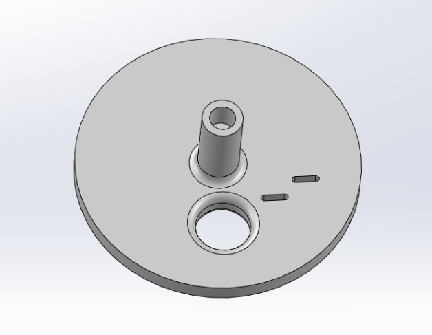
BELL_BASE
This part contains the USB C bulkhead, and clearance holes for attaching the BELL_Holder. It also contains 4x holes for heat-set inserts. This let’s us attach the BELL_BASE to the LED_BASE.
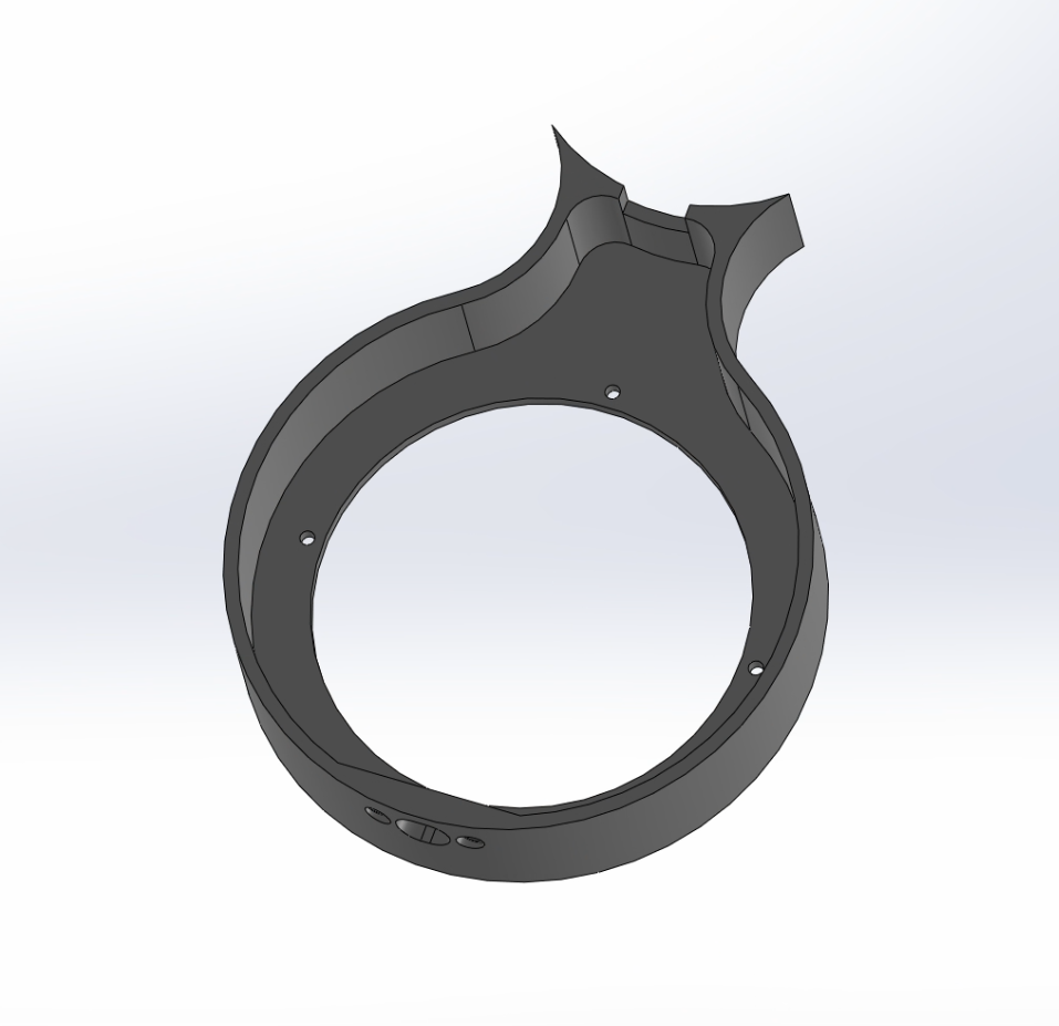
LED_BASE
The LED_BASE contains clearance holes for attaching to the BELL_BASE and for the LED_Holder. It also contains a feature for wall-mounting that’s 3D printer friendly.
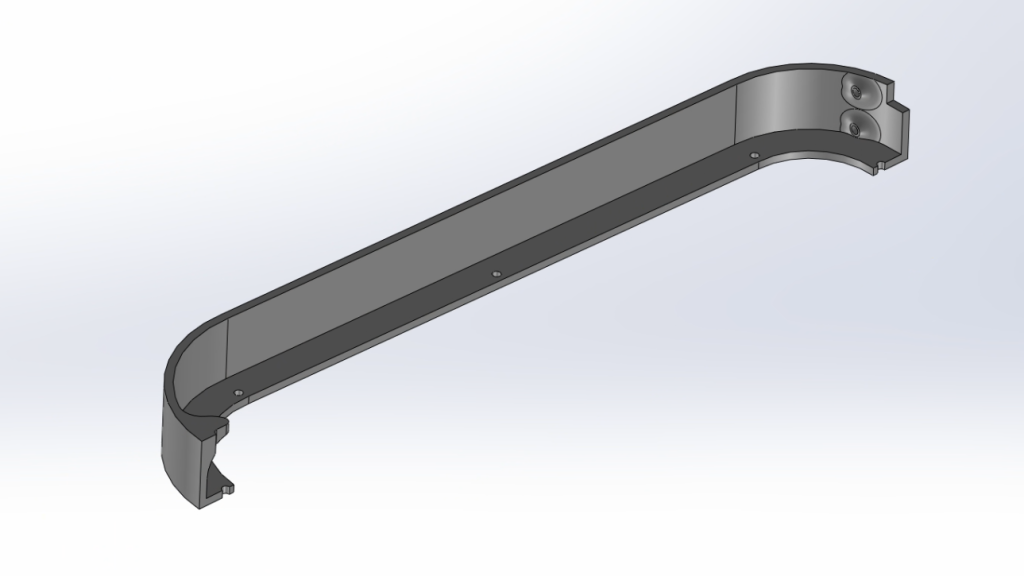
LED_HOLDER_BLOCKER and LED_Holder
This is a multi-color print. I wanted to get around the light bleed so I could have nice crisp pixels but honestly I don’t think it mattered as much and the black light shield shows up through the print like Cousin Eddie’s dickey.

This gets printed as one piece, you can just set the color of the blocker to white as well and you won’t get such an ugly print. I’m not going to do that because there’s approximately 15 heat-set inserts I would need to throw out.
To test fitment I did 3D print the whole piece and a cutaway view so I could see any tolerancing issues I had with the LED panels (there were none!)
BELL_Holder
The bell holder does what the name describes. It holds the bell. There’s two slots for positioning a 12V solenoid, a hole for fishing the solenoid up through, a heat-set insert hole for the bell bolt and 4x 2mm heat-set inserts on the bottom for attaching to the BELL_BASE. The only unpopular thing about this part is there’s no good orientation to print it. There’s a lip at the bottom to center it in the BELL_BASE. I suppose this lip could be removed but with it in, you need to enable supports and it looks kind of crappy coming off the printer.
LED_CLAMP
The LED_CLAMP does what the name implies, it clamps the LED panels to the LED_Holder. I didn’t want to glue the panels in. I also wanted hooks in place for zip-tying my proto board to the unit as a whole as that bit was an after-though. The squares on the print are for feeding through the wires. I really should have left them as cutouts so you can install this and then fish the wires around. It’s a bit fiddley.
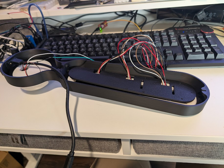
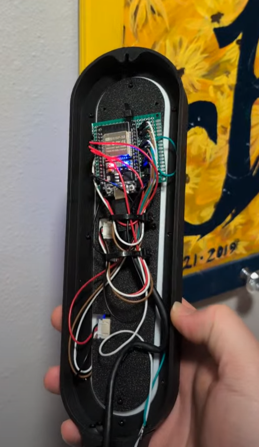
Electrical Design
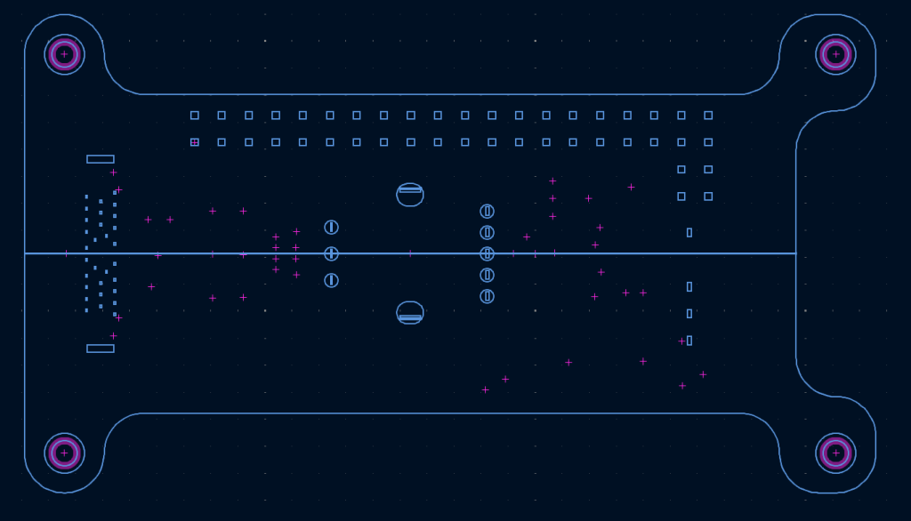
I had a lot of fun just throwing shit on to a proto board. Normally I would do a PCB but at the time of doing this project I have five concurrent PCB projects going at work and at home and am a bit burned out. I’m also learning Altium for work so my brain is just…full. The best you’ll get is a Powerpoint drawing of everything.
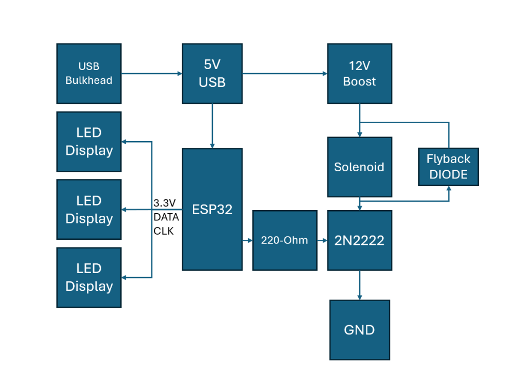
Nothing super special here. The solenoid draws like 200mA always-on. The ESP32 does have a current limit so we’re actually close to not being in saturation. Practically, I don’t see any issues with this.
The LED displays run on 3.3V power from the ESP32 and I was worried about the linear regulator providing power for 3 full panels and the on-board WiFi. I put the panels into a test mode (full on) and left them powered for about an hour. No noticeable heating to the voltage regulator.
Other Parts (Amazon Links and AliExpress Links)
| Item | Quantity | Note |
| 12V Solenoid | 1 | |
| LED Panel | 4 | |
| Bell | ||
| M2 Screws | A Few | Various sizes, test fitment. |
| M2 Heat Set Insert | A Few | |
| M6 Heat Set Insert | 1 | bell mount |
| Proto Board | 1 | |
| ESP32 Dev Board | 1 | |
| 2N2222 NPN | 1 | Some random 2N2222 I had in a kit |
| Diode | 1 | Some random diode I had laying around. No link here. |
| Silicone Wire | 1 | 28GA is what I use. |
| Boost Converter | 1 | 20 Pack |
| USB Bulkhead | 1 | Tight fit, but the screws seat it firmly in place |
| 80-grit sand paper | 1 |
Other Notes
The only real work/modifications that need done are the proto board needed trimmed down to fit inside the “!” and the LED panels needed sanded down to fit in a nice-uninterrupted row.
The LED board can safely be sanded down along it’s length. Unfortunately given the pitch of the LEDs you need to get quite close to them. Take sanding slow and it’ll all go well. I’ve also included extra length for the top and bottom panels so you only have to sand 4x sides instead of 6x sides.
Code
Disclaimer: This was 100% vibe coded but based loosely on UPIRs Code.
The code requirements are as follows:
- OTA Firmware Updates for remote upgrades/tweaks
- WIFI web server for debugging
- MQTT connection
- MQTT advertisement of variables
- GPIO Control (solenoid)
- 3x LED Panel Support
With these requirements and some example code I fed to chatGPT I got the following “finished” code.
Arduino Code, change variables to suit your needs.
/*
  ESP32 Display + Dinger Combo (FULL)

  - 3x Keyestudio 8x16 LED matrix panels stacked vertically => 8w x 48h
      TOP:    SCL=22 SDA=23
      MID:    SCL=18 SDA=19
      BOTTOM: SCL=2  SDA=4

  - Solenoid bell striker on GPIO15 (PULSE_PIN)
  - MQTT discovery (SMALL payloads) for:
      * Button: Ding
      * Number: Ding count (1..3)
      * Number: Pulse width (ms)
      * Number: Gap (ms)
      * Text: Display message (Home Assistant text entity)
  - MQTT command topics (also usable directly):
      * home/dinger/<deviceId>/ding/press          payload: PRESS
      * home/dinger/<deviceId>/ding_count/set      payload: 1..3
      * home/dinger/<deviceId>/pulse_width_ms/set  payload: 1..2000
      * home/dinger/<deviceId>/gap_ms/set          payload: 0..5000
      * home/dinger/<deviceId>/display/set         payload: string
      * home/dinger/<deviceId>/max_current/set     payload: 0/1

  - Web UI:
      * Set count/width/gap + Ding
      * Set display text
      * Max-current test toggle (all LEDs on all panels)
  - OTA enabled

  Notes:
  - GPIO15 is a strapping pin on some ESP32 boards; move if boot issues.
  - Display scroll direction is TOP -> BOTTOM when message length > 6 chars (48/8).
*/

#include <Arduino.h>
#include <WiFi.h>
#include <PubSubClient.h>
#include <ArduinoOTA.h>
#include <WebServer.h>

// ---------- WIFI ----------
const char* WIFI_SSIDS[] = { "SSID1", "SSID2" };
const int WIFI_SSID_COUNT = sizeof(WIFI_SSIDS) / sizeof(WIFI_SSIDS[0]);
const char* WIFI_PASSWORD  = "PASSWORD";

// ---------- MQTT ----------
const char* MQTT_HOST      = "homeassistant.local";
const uint16_t MQTT_PORT   = 1883;
const char* MQTT_USER      = "MQTTUSER";
const char* MQTT_PASS      = "MQTTPASS";

// OTA password
const char* OTA_PASSWORD   = "OTAPASS";

#ifndef LED_BUILTIN
#define LED_BUILTIN 2
#endif

// ---------- HARDWARE ----------
static constexpr uint8_t PULSE_PIN = 15;
static constexpr uint8_t LED_PIN   = LED_BUILTIN;

// 3 panels (top->bottom)
#define SCL_TOP  22
#define SDA_TOP  23
#define SCL_MID  18
#define SDA_MID  19
#define SCL_BOT  2
#define SDA_BOT  4

// ---------- DISPLAY GEOMETRY ----------
static const int PANEL_H = 16;
static const int PANELS  = 3;
static const int DISP_H  = PANEL_H * PANELS; // 48

// ---------- DING LIMITS ----------
static constexpr int      DING_MIN = 1;
static constexpr int      DING_MAX = 5;
static constexpr uint32_t PULSE_MIN_MS = 1;
static constexpr uint32_t PULSE_MAX_MS = 2000;
static constexpr uint32_t GAP_MIN_MS   = 0;
static constexpr uint32_t GAP_MAX_MS   = 5000;

// ---------- SCROLL ----------
static const uint16_t SCROLL_STEP_MS = 80;
static const uint16_t HOLD_MS        = 800;

// ---------- GLOBALS ----------
WiFiClient    espClient;
PubSubClient  mqtt(espClient);
WebServer     server(80);

int currentSsidIndex = 0;

// Dinger params
volatile int dingCount = 1;
volatile uint32_t pulseWidthMs = 20;
volatile uint32_t gapMs = 80;

// Dinger state machine (non-blocking, FIXED)
enum DingPhase : uint8_t { DING_IDLE, DING_PULSE_ON, DING_GAP_WAIT };
static DingPhase dingPhase = DING_IDLE;
static int dingRemaining = 0;
static uint32_t phaseUntilMs = 0;

// Display state
static const int MAX_MSG = 96;
char displayText[MAX_MSG] = "I LOVE YOU";
bool maxCurrentTest = false;

// Display buffers
static uint8_t fb[DISP_H];          // visible 48 rows (each row is 8 bits)
static uint8_t* vrows = nullptr;    // virtual rows for scrolling
static int vheightAlloc = 0;
int scrollTopY = 0;
bool scrollHold = false;
uint32_t scrollLastStepMs = 0;
uint32_t scrollHoldStartMs = 0;
uint32_t displayEpoch = 0;          // increment when text changes
uint32_t renderedEpoch = 0;         // last rendered epoch
bool isScrolling = false;

// MQTT topics/IDs
char deviceId[32];
char baseTopic[96];
char availTopic[128];

char dingCmdTopic[128];

char countStateTopic[128];
char countCmdTopic[128];

char widthStateTopic[128];
char widthCmdTopic[128];

char gapStateTopic[128];
char gapCmdTopic[128];

// Display topics
char dispStateTopic[128];
char dispCmdTopic[128];

// Max current topics
char maxTestStateTopic[128];
char maxTestCmdTopic[128];

// Telemetry
uint32_t bootMs = 0;
uint32_t mqttReconnects = 0;
uint32_t lastMqttRxMs = 0;
char lastMqttTopic[128] = {0};
char lastMqttPayload[256] = {0};

// ---------- UTILS ----------
static int clampInt(int v, int lo, int hi) {
  if (v < lo) return lo;
  if (v > hi) return hi;
  return v;
}
static uint32_t clampU32(uint32_t v, uint32_t lo, uint32_t hi) {
  if (v < lo) return lo;
  if (v > hi) return hi;
  return v;
}

static void formatDeviceId() {
  uint32_t macLo = (uint32_t)ESP.getEfuseMac();
  snprintf(deviceId, sizeof(deviceId), "DINGER_%08X", macLo);
}

static void buildTopics() {
  snprintf(baseTopic, sizeof(baseTopic), "home/dinger/%s", deviceId);

  snprintf(availTopic, sizeof(availTopic), "%s/availability", baseTopic);

  snprintf(dingCmdTopic, sizeof(dingCmdTopic), "%s/ding/press", baseTopic);

  snprintf(countStateTopic, sizeof(countStateTopic), "%s/ding_count/state", baseTopic);
  snprintf(countCmdTopic,   sizeof(countCmdTopic),   "%s/ding_count/set",   baseTopic);

  snprintf(widthStateTopic, sizeof(widthStateTopic), "%s/pulse_width_ms/state", baseTopic);
  snprintf(widthCmdTopic,   sizeof(widthCmdTopic),   "%s/pulse_width_ms/set",   baseTopic);

  snprintf(gapStateTopic,   sizeof(gapStateTopic),   "%s/gap_ms/state", baseTopic);
  snprintf(gapCmdTopic,     sizeof(gapCmdTopic),     "%s/gap_ms/set",   baseTopic);

  // Display
  snprintf(dispStateTopic, sizeof(dispStateTopic), "%s/display/state", baseTopic);
  snprintf(dispCmdTopic,   sizeof(dispCmdTopic),   "%s/display/set",   baseTopic);

  // Max current test
  snprintf(maxTestStateTopic, sizeof(maxTestStateTopic), "%s/max_current/state", baseTopic);
  snprintf(maxTestCmdTopic,   sizeof(maxTestCmdTopic),   "%s/max_current/set",   baseTopic);
}

static void publishRetainedU32(const char* topic, uint32_t v) {
  if (!mqtt.connected()) return;
  char buf[16];
  snprintf(buf, sizeof(buf), "%lu", (unsigned long)v);
  mqtt.publish(topic, buf, true);
}
static void publishRetainedI32(const char* topic, int v) {
  if (!mqtt.connected()) return;
  char buf[16];
  snprintf(buf, sizeof(buf), "%d", v);
  mqtt.publish(topic, buf, true);
}
static void publishRetainedStr(const char* topic, const char* s) {
  if (!mqtt.connected()) return;
  mqtt.publish(topic, s, true);
}
static void publishRetainedBool(const char* topic, bool v) {
  if (!mqtt.connected()) return;
  mqtt.publish(topic, v ? "1" : "0", true);
}

// ---------- SOFTWARE I2C (bit-banged) ----------
void IIC_start(uint8_t scl, uint8_t sda) {
  digitalWrite(scl, LOW);  delayMicroseconds(3);
  digitalWrite(sda, HIGH); delayMicroseconds(3);
  digitalWrite(scl, HIGH); delayMicroseconds(3);
  digitalWrite(sda, LOW);  delayMicroseconds(3);
}
void IIC_send(uint8_t scl, uint8_t sda, uint8_t data) {
  for (uint8_t i = 0; i < 8; i++) {
    digitalWrite(scl, LOW); delayMicroseconds(3);
    digitalWrite(sda, (data & 0x01) ? HIGH : LOW);
    delayMicroseconds(3);
    digitalWrite(scl, HIGH); delayMicroseconds(3);
    data >>= 1;
  }
}
void IIC_end(uint8_t scl, uint8_t sda) {
  digitalWrite(scl, LOW);  delayMicroseconds(3);
  digitalWrite(sda, LOW);  delayMicroseconds(3);
  digitalWrite(scl, HIGH); delayMicroseconds(3);
  digitalWrite(sda, HIGH); delayMicroseconds(3);
}

static void setBrightness(uint8_t scl, uint8_t sda, uint8_t brightnessCmd) {
  IIC_start(scl, sda);
  IIC_send(scl, sda, brightnessCmd); // 0x88..0x8F
  IIC_end(scl, sda);
}

static void updateDisp(uint8_t scl, uint8_t sda, uint8_t frame16[16]) {
  IIC_start(scl, sda);
  IIC_send(scl, sda, 0x40); // auto-increment
  IIC_end(scl, sda);

  IIC_start(scl, sda);
  IIC_send(scl, sda, 0xC0); // start addr 0
  for (uint8_t i = 0; i < 16; i++) IIC_send(scl, sda, frame16[i]);
  IIC_end(scl, sda);
}

// ---------- DISPLAY RENDERING ----------
static inline void fbClear() { memset(fb, 0, sizeof(fb)); }

// 8x8 font A-Z, 0-9, space
struct Glyph { char c; uint8_t rows[8]; };
static const Glyph font[] = {
  { ' ', {0x00,0x00,0x00,0x00,0x00,0x00,0x00,0x00} },

  { '0', {0x3C,0x66,0x6E,0x76,0x66,0x66,0x3C,0x00} },
  { '1', {0x18,0x38,0x18,0x18,0x18,0x18,0x3C,0x00} },
  { '2', {0x3C,0x66,0x06,0x0C,0x18,0x30,0x7E,0x00} },
  { '3', {0x3C,0x66,0x06,0x1C,0x06,0x66,0x3C,0x00} },
  { '4', {0x0C,0x1C,0x3C,0x6C,0x7E,0x0C,0x0C,0x00} },
  { '5', {0x7E,0x60,0x7C,0x06,0x06,0x66,0x3C,0x00} },
  { '6', {0x1C,0x30,0x60,0x7C,0x66,0x66,0x3C,0x00} },
  { '7', {0x7E,0x66,0x06,0x0C,0x18,0x18,0x18,0x00} },
  { '8', {0x3C,0x66,0x66,0x3C,0x66,0x66,0x3C,0x00} },
  { '9', {0x3C,0x66,0x66,0x3E,0x06,0x0C,0x38,0x00} },

  { 'A', {0x18,0x24,0x42,0x7E,0x42,0x42,0x42,0x00} },
  { 'B', {0x7C,0x42,0x42,0x7C,0x42,0x42,0x7C,0x00} },
  { 'C', {0x3C,0x42,0x40,0x40,0x40,0x42,0x3C,0x00} },
  { 'D', {0x78,0x44,0x42,0x42,0x42,0x44,0x78,0x00} },
  { 'E', {0x7E,0x40,0x40,0x7C,0x40,0x40,0x7E,0x00} },
  { 'F', {0x7E,0x40,0x40,0x7C,0x40,0x40,0x40,0x00} },
  { 'G', {0x3C,0x42,0x40,0x4E,0x42,0x42,0x3C,0x00} },
  { 'H', {0x42,0x42,0x42,0x7E,0x42,0x42,0x42,0x00} },
  { 'I', {0x7E,0x18,0x18,0x18,0x18,0x18,0x7E,0x00} },
  { 'J', {0x0E,0x04,0x04,0x04,0x44,0x44,0x38,0x00} },
  { 'K', {0x42,0x44,0x48,0x70,0x48,0x44,0x42,0x00} },
  { 'L', {0x40,0x40,0x40,0x40,0x40,0x40,0x7E,0x00} },
  { 'M', {0x42,0x66,0x5A,0x5A,0x42,0x42,0x42,0x00} },
  { 'N', {0x42,0x62,0x52,0x4A,0x46,0x42,0x42,0x00} },
  { 'O', {0x3C,0x42,0x42,0x42,0x42,0x42,0x3C,0x00} },
  { 'P', {0x7C,0x42,0x42,0x7C,0x40,0x40,0x40,0x00} },
  { 'Q', {0x3C,0x42,0x42,0x42,0x4A,0x44,0x3A,0x00} },
  { 'R', {0x7C,0x42,0x42,0x7C,0x48,0x44,0x42,0x00} },
  { 'S', {0x3C,0x42,0x40,0x3C,0x02,0x42,0x3C,0x00} },
  { 'T', {0x7E,0x18,0x18,0x18,0x18,0x18,0x18,0x00} },
  { 'U', {0x42,0x42,0x42,0x42,0x42,0x42,0x3C,0x00} },
  { 'V', {0x42,0x42,0x42,0x42,0x24,0x24,0x18,0x00} },
  { 'W', {0x42,0x42,0x42,0x5A,0x5A,0x66,0x42,0x00} },
  { 'X', {0x42,0x24,0x18,0x18,0x18,0x24,0x42,0x00} },
  { 'Y', {0x42,0x24,0x18,0x18,0x18,0x18,0x18,0x00} },
  { 'Z', {0x7E,0x02,0x04,0x18,0x20,0x40,0x7E,0x00} },
};

static const uint8_t* glyphRows(char c) {
  if (c >= 'a' && c <= 'z') c = char(c - 'a' + 'A');
  for (size_t i=0; i<sizeof(font)/sizeof(font[0]); i++) {
    if (font[i].c == c) return font[i].rows;
  }
  return font[0].rows;
}

static int msgLen(const char* s) { int n=0; while (*s++) n++; return n; }

static void ensureVirtualHeight(int vheight) {
  if (vheightAlloc == vheight && vrows) return;
  if (vrows) free(vrows);
  vrows = (uint8_t*)malloc(vheight);
  vheightAlloc = vrows ? vheight : 0;
}

static void renderToVirtual(const char* msg) {
  const int n = msgLen(msg);
  const int messageHeight = n * 8;             // 8px per char, no gap
  const int vheight = messageHeight + DISP_H;  // pad for entry/exit
  ensureVirtualHeight(vheight);
  if (!vrows) return;

  memset(vrows, 0, vheight);
  int y = 0;
  for (const char* p = msg; *p; p++) {
    const uint8_t* r = glyphRows(*p);
    for (int dy=0; dy<8; dy++) {
      int yy = y + dy;
      if (yy >= 0 && yy < vheight) vrows[yy] = r[dy];
    }
    y += 8;
    if (y >= vheight) break;
  }

  isScrolling = (n > (DISP_H / 8)); // >6 chars
  scrollTopY = -DISP_H;             // start above view
  scrollHold = false;
  scrollLastStepMs = millis();
}

static void windowFromVirtual(int topY) {
  if (!vrows || vheightAlloc <= 0) { fbClear(); return; }
  for (int y=0; y<DISP_H; y++) {
    int srcY = topY + y;
    fb[y] = (srcY >= 0 && srcY < vheightAlloc) ? vrows[srcY] : 0x00;
  }
}

// If mirrored/flipped, fix ONLY here.
static void pushFbToPanels() {
  uint8_t fTop[16], fMid[16], fBot[16];
  for (int i=0; i<16; i++) fTop[i] = fb[0  + i];
  for (int i=0; i<16; i++) fMid[i] = fb[16 + i];
  for (int i=0; i<16; i++) fBot[i] = fb[32 + i];

  updateDisp(SCL_TOP, SDA_TOP, fTop);
  updateDisp(SCL_MID, SDA_MID, fMid);
  updateDisp(SCL_BOT, SDA_BOT, fBot);
}

static void allLedsOnAllPanels() {
  uint8_t on16[16];
  for (int i=0; i<16; i++) on16[i] = 0xFF;
  updateDisp(SCL_TOP, SDA_TOP, on16);
  updateDisp(SCL_MID, SDA_MID, on16);
  updateDisp(SCL_BOT, SDA_BOT, on16);
}

static void setDisplayText(const char* s) {
  // sanitize to A-Z 0-9 space (unknown -> space)
  size_t n = strnlen(s, MAX_MSG - 1);
  for (size_t i = 0; i < n; i++) {
    char c = s[i];
    if (c >= 'a' && c <= 'z') c = char(c - 'a' + 'A');
    bool ok = (c == ' ') || (c >= 'A' && c <= 'Z') || (c >= '0' && c <= '9');
    displayText[i] = ok ? c : ' ';
  }
  displayText[n] = '\0';

  displayEpoch++;
  publishRetainedStr(dispStateTopic, displayText);
}

// ---------- DINGER (non-blocking, FIXED) ----------
static void startDings(int n) {
  if (dingPhase != DING_IDLE) return;
  n = clampInt(n, DING_MIN, DING_MAX);
  dingRemaining = n;
  dingPhase = DING_PULSE_ON;
  phaseUntilMs = 0; // start immediately
}

static void serviceDinger() {
  const uint32_t now = millis();
  if (dingPhase == DING_IDLE) return;

  if (phaseUntilMs && (int32_t)(now - phaseUntilMs) < 0) return;

  const uint32_t w = clampU32(pulseWidthMs, PULSE_MIN_MS, PULSE_MAX_MS);
  const uint32_t g = clampU32(gapMs, GAP_MIN_MS, GAP_MAX_MS);

  switch (dingPhase) {
    case DING_PULSE_ON:
      // start pulse
      digitalWrite(PULSE_PIN, HIGH);
      digitalWrite(LED_PIN, HIGH);
      dingPhase = DING_GAP_WAIT;
      phaseUntilMs = now + w;
      break;

    case DING_GAP_WAIT:
      // end pulse
      digitalWrite(PULSE_PIN, LOW);
      digitalWrite(LED_PIN, LOW);

      dingRemaining--;
      if (dingRemaining <= 0) {
        dingPhase = DING_IDLE;
        phaseUntilMs = 0;
      } else {
        // wait gap before next pulse
        dingPhase = DING_PULSE_ON;
        phaseUntilMs = now + g;
      }
      break;

    default:
      dingPhase = DING_IDLE;
      phaseUntilMs = 0;
      break;
  }
}

// ---------- WIFI ----------
void connectWiFi() {
  if (WiFi.status() == WL_CONNECTED) return;

  WiFi.mode(WIFI_STA);

  while (WiFi.status() != WL_CONNECTED) {
    const char* ssid = WIFI_SSIDS[currentSsidIndex];
    Serial.printf("Connecting to WiFi SSID: %s\n", ssid);
    WiFi.begin(ssid, WIFI_PASSWORD);

    int attempts = 0;
    while (WiFi.status() != WL_CONNECTED && attempts < 20) {
      delay(500);
      Serial.print(".");
      attempts++;
    }

    if (WiFi.status() == WL_CONNECTED) {
      Serial.print("\nConnected to ");
      Serial.print(ssid);
      Serial.print(", IP=");
      Serial.println(WiFi.localIP());
      break;
    } else {
      Serial.printf("\nFailed to connect to %s\n", ssid);
      currentSsidIndex = (currentSsidIndex + 1) % WIFI_SSID_COUNT;
      delay(1000);
    }
  }
}

// ---------- MQTT DISCOVERY ----------
static void publishDiscoverySmall() {
  if (!mqtt.connected()) return;

  char cfgTopic[128];
  char payload[256];

  // Button (ding)
  snprintf(cfgTopic, sizeof(cfgTopic), "homeassistant/button/%s/ding/config", deviceId);
  snprintf(payload, sizeof(payload),
           "{\"name\":\"%s Ding\",\"unique_id\":\"%s_ding\","
           "\"command_topic\":\"%s\",\"payload_press\":\"PRESS\"}",
           deviceId, deviceId, dingCmdTopic);
  mqtt.publish(cfgTopic, payload, true);

  // Number: Ding Count
  snprintf(cfgTopic, sizeof(cfgTopic), "homeassistant/number/%s/ding_count/config", deviceId);
  snprintf(payload, sizeof(payload),
           "{\"name\":\"%s Ding Count\",\"unique_id\":\"%s_ding_count\","
           "\"state_topic\":\"%s\",\"command_topic\":\"%s\","
           "\"min\":1,\"max\":5,\"step\":1,\"mode\":\"slider\"}",
           deviceId, deviceId, countStateTopic, countCmdTopic);
  mqtt.publish(cfgTopic, payload, true);

  // Number: Pulse Width (ms)
  snprintf(cfgTopic, sizeof(cfgTopic), "homeassistant/number/%s/pulse_width_ms/config", deviceId);
  snprintf(payload, sizeof(payload),
           "{\"name\":\"%s Pulse Width (ms)\",\"unique_id\":\"%s_pulse_width_ms\","
           "\"state_topic\":\"%s\",\"command_topic\":\"%s\","
           "\"min\":%lu,\"max\":%lu,\"step\":1,\"mode\":\"slider\"}",
           deviceId, deviceId, widthStateTopic, widthCmdTopic,
           (unsigned long)PULSE_MIN_MS, (unsigned long)PULSE_MAX_MS);
  mqtt.publish(cfgTopic, payload, true);

  // Number: Gap (ms)
  snprintf(cfgTopic, sizeof(cfgTopic), "homeassistant/number/%s/gap_ms/config", deviceId);
  snprintf(payload, sizeof(payload),
           "{\"name\":\"%s Gap (ms)\",\"unique_id\":\"%s_gap_ms\","
           "\"state_topic\":\"%s\",\"command_topic\":\"%s\","
           "\"min\":50,\"max\":500,\"step\":50,\"mode\":\"slider\"}",
           deviceId, deviceId, gapStateTopic, gapCmdTopic,
           (unsigned long)GAP_MIN_MS, (unsigned long)GAP_MAX_MS);
  mqtt.publish(cfgTopic, payload, true);

  // Text: Display Message (THIS MAKES text.<device>_display appear)
  snprintf(cfgTopic, sizeof(cfgTopic), "homeassistant/text/%s/display/config", deviceId);
  snprintf(payload, sizeof(payload),
           "{\"name\":\"%s Display\",\"unique_id\":\"%s_display\","
           "\"state_topic\":\"%s\",\"command_topic\":\"%s\","
           "\"max\":95,\"mode\":\"text\"}",
           deviceId, deviceId, dispStateTopic, dispCmdTopic);
  mqtt.publish(cfgTopic, payload, true);
}

// ---------- MQTT CALLBACK ----------
void mqttCallback(char* topic, byte* payload, unsigned int length) {
  lastMqttRxMs = millis();
  strncpy(lastMqttTopic, topic, sizeof(lastMqttTopic) - 1);
  lastMqttTopic[sizeof(lastMqttTopic) - 1] = '\0';

  unsigned int n = (length < (sizeof(lastMqttPayload) - 1)) ? length : (sizeof(lastMqttPayload) - 1);
  for (unsigned int i = 0; i < n; i++) lastMqttPayload[i] = (char)payload[i];
  lastMqttPayload[n] = '\0';

  if (strcmp(topic, countCmdTopic) == 0) {
    dingCount = clampInt(atoi(lastMqttPayload), DING_MIN, DING_MAX);
    publishRetainedI32(countStateTopic, dingCount);
    return;
  }
  if (strcmp(topic, widthCmdTopic) == 0) {
    pulseWidthMs = clampU32((uint32_t)atoi(lastMqttPayload), PULSE_MIN_MS, PULSE_MAX_MS);
    publishRetainedU32(widthStateTopic, pulseWidthMs);
    return;
  }
  if (strcmp(topic, gapCmdTopic) == 0) {
    gapMs = clampU32((uint32_t)atoi(lastMqttPayload), GAP_MIN_MS, GAP_MAX_MS);
    publishRetainedU32(gapStateTopic, gapMs);
    return;
  }
  if (strcmp(topic, dingCmdTopic) == 0) {
    startDings(dingCount);
    return;
  }

  if (strcmp(topic, dispCmdTopic) == 0) {
    setDisplayText(lastMqttPayload);
    return;
  }

  if (strcmp(topic, maxTestCmdTopic) == 0) {
    int v = atoi(lastMqttPayload);
    maxCurrentTest = (v != 0);
    publishRetainedBool(maxTestStateTopic, maxCurrentTest);
    return;
  }
}

void connectMQTT() {
  mqtt.setServer(MQTT_HOST, MQTT_PORT);
  mqtt.setCallback(mqttCallback);
  mqtt.setBufferSize(512);

  while (!mqtt.connected()) {
    mqttReconnects++;

    bool ok = mqtt.connect(
      deviceId,
      MQTT_USER,
      MQTT_PASS,
      availTopic,
      0,
      true,
      "offline"
    );

    if (ok) {
      mqtt.publish(availTopic, "online", true);

      mqtt.subscribe(dingCmdTopic);
      mqtt.subscribe(countCmdTopic);
      mqtt.subscribe(widthCmdTopic);
      mqtt.subscribe(gapCmdTopic);
      mqtt.subscribe(dispCmdTopic);
      mqtt.subscribe(maxTestCmdTopic);

      publishDiscoverySmall();

      publishRetainedI32(countStateTopic, dingCount);
      publishRetainedU32(widthStateTopic, pulseWidthMs);
      publishRetainedU32(gapStateTopic, gapMs);
      publishRetainedStr(dispStateTopic, displayText);
      publishRetainedBool(maxTestStateTopic, maxCurrentTest);

    } else {
      Serial.print("MQTT failed rc=");
      Serial.println(mqtt.state());
      delay(2000);
    }
  }
}

// ---------- WEB ----------
static String statusJson() {
  bool wifiOk = (WiFi.status() == WL_CONNECTED);
  bool mqttOk = mqtt.connected();
  int rssi = wifiOk ? WiFi.RSSI() : -999;

  uint32_t upS = (millis() - bootMs) / 1000;
  uint32_t lastAgeMs = (lastMqttRxMs == 0) ? 0 : (millis() - lastMqttRxMs);

  String ip = wifiOk ? WiFi.localIP().toString() : "0.0.0.0";

  String j;
  j.reserve(1000);
  j += "{";
  j += "\"device_id\":\""; j += deviceId; j += "\",";
  j += "\"ip\":\""; j += ip; j += "\",";
  j += "\"rssi\":"; j += String(rssi); j += ",";
  j += "\"mqtt_connected\":"; j += (mqttOk ? "true" : "false"); j += ",";
  j += "\"mqtt_state\":"; j += String(mqtt.state()); j += ",";
  j += "\"mqtt_reconnects\":"; j += String(mqttReconnects); j += ",";
  j += "\"ding_count\":"; j += String(dingCount); j += ",";
  j += "\"pulse_width_ms\":"; j += String(pulseWidthMs); j += ",";
  j += "\"gap_ms\":"; j += String(gapMs); j += ",";
  j += "\"ding_phase\":"; j += String((int)dingPhase); j += ",";
  j += "\"display_text\":\""; j += displayText; j += "\",";
  j += "\"max_current_test\":"; j += (maxCurrentTest ? "true" : "false"); j += ",";
  j += "\"uptime_s\":"; j += String(upS); j += ",";
  j += "\"last_mqtt_topic\":\""; j += lastMqttTopic; j += "\",";
  j += "\"last_mqtt_payload\":\""; j += lastMqttPayload; j += "\",";
  j += "\"last_mqtt_age_ms\":"; j += String(lastAgeMs);
  j += "}";
  return j;
}

void handleRoot() {
  server.send(200, "text/html",
    "<!doctype html><html><head><meta name='viewport' content='width=device-width,initial-scale=1'>"
    "<title>Dinger + Display</title>"
    "<style>body{font-family:system-ui;margin:20px;max-width:860px}"
    "input{font-size:18px;padding:6px 8px} "
    "button{font-size:18px;padding:10px 16px;margin:6px 8px 6px 0} "
    "pre{background:#111;color:#eee;padding:12px;border-radius:10px;overflow:auto}"
    ".row{margin:10px 0}</style></head><body>"
    "<h2>Dinger + Display</h2>"

    "<div class='row'>Ding count (1..3): <input id='count' type='number' min='1' max='3' step='1'></div>"
    "<div class='row'>Pulse width (ms): <input id='width' type='number' min='1' step='1'></div>"
    "<div class='row'>Gap (ms): <input id='gap' type='number' min='0' step='1'></div>"
    "<button onclick='applyDing()'>Apply</button>"
    "<button onclick='fire()'>Ding</button>"

    "<hr>"

    "<div class='row'>Display text: <input id='msg' type='text' style='width:420px' maxlength='95'></div>"
    "<button onclick='applyMsg()'>Set Display</button>"
    "<button onclick='maxOn()'>Max Current ON</button>"
    "<button onclick='maxOff()'>Max Current OFF</button>"

    "<h3>Status</h3><pre id='st'>loading...</pre>"

    "<script>"
    "async function getStatus(){"
    " const r=await fetch('/status'); const j=await r.json();"
    " document.getElementById('st').textContent=JSON.stringify(j,null,2);"
    " if(document.activeElement.id!=='count') document.getElementById('count').value=j.ding_count;"
    " if(document.activeElement.id!=='width') document.getElementById('width').value=j.pulse_width_ms;"
    " if(document.activeElement.id!=='gap') document.getElementById('gap').value=j.gap_ms;"
    " if(document.activeElement.id!=='msg') document.getElementById('msg').value=j.display_text;"
    "}"
    "async function applyDing(){"
    " const c=document.getElementById('count').value|0;"
    " const w=document.getElementById('width').value|0;"
    " const g=document.getElementById('gap').value|0;"
    " await fetch(`/set_ding?count=${c}&width=${w}&gap=${g}`); await getStatus();"
    "}"
    "async function fire(){ await fetch('/fire'); await getStatus(); }"
    "async function applyMsg(){"
    " const m=encodeURIComponent(document.getElementById('msg').value);"
    " await fetch(`/set_msg?m=${m}`); await getStatus();"
    "}"
    "async function maxOn(){ await fetch('/max?on=1'); await getStatus(); }"
    "async function maxOff(){ await fetch('/max?on=0'); await getStatus(); }"
    "setInterval(getStatus,1000); getStatus();"
    "</script></body></html>"
  );
}

void handleStatus() { server.send(200, "application/json", statusJson()); }

void handleSetDing() {
  if (server.hasArg("count")) dingCount = clampInt(server.arg("count").toInt(), DING_MIN, DING_MAX);
  if (server.hasArg("width")) pulseWidthMs = clampU32((uint32_t)server.arg("width").toInt(), PULSE_MIN_MS, PULSE_MAX_MS);
  if (server.hasArg("gap"))   gapMs       = clampU32((uint32_t)server.arg("gap").toInt(),   GAP_MIN_MS,   GAP_MAX_MS);

  publishRetainedI32(countStateTopic, dingCount);
  publishRetainedU32(widthStateTopic, pulseWidthMs);
  publishRetainedU32(gapStateTopic, gapMs);

  server.send(200, "text/plain", "OK");
}

void handleFire() {
  startDings(dingCount);
  server.send(200, "text/plain", "OK");
}

void handleSetMsg() {
  if (server.hasArg("m")) {
    String m = server.arg("m"); // decoded
    setDisplayText(m.c_str());
  }
  server.send(200, "text/plain", "OK");
}

void handleMax() {
  int on = server.hasArg("on") ? server.arg("on").toInt() : 0;
  maxCurrentTest = (on != 0);
  publishRetainedBool(maxTestStateTopic, maxCurrentTest);
  server.send(200, "text/plain", "OK");
}

// ---------- DISPLAY SERVICE (non-blocking) ----------
static void serviceDisplay() {
  if (maxCurrentTest) {
    allLedsOnAllPanels();
    return;
  }

  if (renderedEpoch != displayEpoch) {
    renderToVirtual(displayText);
    renderedEpoch = displayEpoch;
  }

  const uint32_t now = millis();

  if (!isScrolling) {
    fbClear();
    int n = msgLen(displayText);
    int maxStatic = DISP_H / 8; // 6
    for (int i=0; i<n && i<maxStatic; i++) {
      const uint8_t* r = glyphRows(displayText[i]);
      for (int dy=0; dy<8; dy++) {
        fb[i*8 + dy] = r[dy];
      }
    }
    pushFbToPanels();
    return;
  }

  if (scrollHold) {
    if (now - scrollHoldStartMs >= HOLD_MS) {
      scrollHold = false;
      scrollLastStepMs = now;
    } else {
      windowFromVirtual(scrollTopY);
      pushFbToPanels();
      return;
    }
  }

  if (now - scrollLastStepMs >= SCROLL_STEP_MS) {
    scrollLastStepMs = now;
    scrollTopY++; // TOP -> BOTTOM
    if (vrows && vheightAlloc > 0) {
      if (scrollTopY > (vheightAlloc - DISP_H)) {
        scrollTopY = -DISP_H;
        scrollHold = true;
        scrollHoldStartMs = now;
      }
    }
  }

  windowFromVirtual(scrollTopY);
  pushFbToPanels();
}

// ---------- OTA ----------
static void setupOTA() {
  ArduinoOTA.setHostname(deviceId);
  if (OTA_PASSWORD && OTA_PASSWORD[0] != '\0') ArduinoOTA.setPassword(OTA_PASSWORD);
  ArduinoOTA.begin();
}

// ---------- SETUP / LOOP ----------
void setup() {
  Serial.begin(115200);
  delay(300);
  bootMs = millis();

  // Dinger pins
  pinMode(PULSE_PIN, OUTPUT);
  digitalWrite(PULSE_PIN, LOW);
  pinMode(LED_PIN, OUTPUT);
  digitalWrite(LED_PIN, LOW);

  // Display pins
  pinMode(SCL_TOP, OUTPUT); pinMode(SDA_TOP, OUTPUT);
  pinMode(SCL_MID, OUTPUT); pinMode(SDA_MID, OUTPUT);
  pinMode(SCL_BOT, OUTPUT); pinMode(SDA_BOT, OUTPUT);

  digitalWrite(SCL_TOP, LOW); digitalWrite(SDA_TOP, LOW);
  digitalWrite(SCL_MID, LOW); digitalWrite(SDA_MID, LOW);
  digitalWrite(SCL_BOT, LOW); digitalWrite(SDA_BOT, LOW);

  // Brightness
  setBrightness(SCL_TOP, SDA_TOP, 0x8E);
  setBrightness(SCL_MID, SDA_MID, 0x8E);
  setBrightness(SCL_BOT, SDA_BOT, 0x8E);

  // IDs/topics
  formatDeviceId();
  buildTopics();

  // WiFi
  connectWiFi();

  // OTA
  setupOTA();

  // MQTT
  mqtt.setCallback(mqttCallback);
  connectMQTT();

  // Web
  server.on("/", handleRoot);
  server.on("/status", handleStatus);
  server.on("/set_ding", handleSetDing);
  server.on("/fire", handleFire);
  server.on("/set_msg", handleSetMsg);
  server.on("/max", handleMax);
  server.begin();

  // Init display
  setDisplayText(displayText);
  renderToVirtual(displayText);
  renderedEpoch = displayEpoch;
}

void loop() {
  ArduinoOTA.handle();

  if (WiFi.status() != WL_CONNECTED) connectWiFi();
  if (!mqtt.connected()) connectMQTT();
  mqtt.loop();

  server.handleClient();

  serviceDinger();
  serviceDisplay();
}
Wifi supports multiple networks. So you can test and deploy between multiple locations (like if you’re giving this to a friend).
The board to use for these generic ESP-32’s is DOIT ESP32 DEVKIT V1
Home Assistant Integration
Since the code above contains auto-discovery you can easily write your own dashboard for this unit. The main breakouts are:
- Ding
- Ding Count
- Pulse Width (how long the solenoid stays on for)
- Gap (gap between dings)
- Text (display message)
Once the MQTT “sensors” are discovered you can make a quick dashboard to test out basic functionality. Keep in mind that the “dinger” sensor is followed by the ESP’s MAC address so you can have multiple of these units. The below HomeAssistant integration code won’t work for you, but you should be able to use your own mac address (advertised) and be up and running.
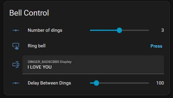
Bell Control Dashboard Code
type: entities
title: Bell Control
entities:
  - entity: number.dinger_8ad8cbb0_ding_count
    name: Number of dings
  - entity: button.dinger_8ad8cbb0_ding
    name: Ring bell
  - entity: text.dinger_8ad8cbb0_display
  - entity: number.dinger_8ad8cbb0_gap_ms
    name: Delay Between Dings
grid_options:
  columns: 12
  rows: auto
Once you’re happy with the manual control, you’ll want to get some automation hooks in. This allows for 1-press canned messages and for integration with other sensors (like a mailbox or road sensor).
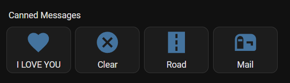
Canned Messages Dashboard Code
type: horizontal-stack
cards:
  - show_name: true
    show_icon: true
    type: button
    name: I LOVE YOU
    icon: mdi:heart
    tap_action:
      action: perform-action
      target:
        entity_id: automation.dinger_love_you
      perform_action: automation.trigger
      data:
        skip_condition: true
  - type: button
    name: Clear
    icon: mdi:close-circle
    tap_action:
      action: call-service
      service: automation.trigger
      target:
        entity_id: automation.dinger_clear_display
  - type: button
    name: Road
    icon: mdi:road
    tap_action:
      action: call-service
      service: automation.trigger
      target:
        entitity_id: automation.road_notification_dinger
  - type: button
    name: Mail
    icon: mdi:mailbox
    tap_action:
      action: call-service
      service: automation.trigger
      target:
        entitity_id: automation.mail
For the canned messages to work, you need to have automations written on the back end for each of the buttons to call. Here are a couple automations you can use:
Clear Automation (Clears the LED Display)
alias: dinger_clear_display
description: ""
triggers:
  - trigger: event
    event_type: ""
conditions: []
actions:
  - action: text.set_value
    metadata: {}
    target:
      entity_id: text.dinger_8ad8cbb0_display
    data:
      value: ""
mode: single
I LOVE YOU Automation (Dings the bell 3 times, and displays “I LOVE YOU” on the LED Display)
alias: dinger_love_you
description: ""
triggers:
  - trigger: event
    event_type: ""
conditions: []
actions:
  - action: text.set_value
    metadata: {}
    target:
      entity_id: text.dinger_8ad8cbb0_display
    data:
      value: I LOVE YOU
  - action: number.set_value
    metadata: {}
    target:
      entity_id: number.dinger_8ad8cbb0_ding_count
    data:
      value: "3"
  - action: button.press
    metadata: {}
    target:
      entity_id: button.dinger_8ad8cbb0_ding
    data: {}
mode: single
Project Files
My code is pasted above in the Code section. The 3D files are available for download, modification, or printing on Printables and MakerWorld.
Final Thoughts
The ! Notifier was fun to design and I hope to see others use or remix the design for their own use!
Errata
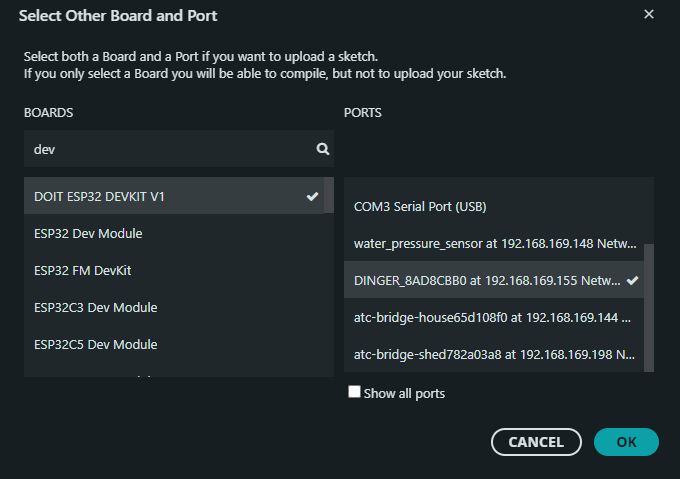
The ESP32 I use works just great when called a “DOIT ESP32 DEVKIT V1” that’s not what it’s called on amazon.