
I’m what you might call a casual mechanical engineer. By trade, I’m an electrical engineer, but there’s something cathartic about designing parts in solidworks. I started off in high school and didn’t think much of it, but as I went through college I contracted out my skills to model up jewelry for clients. This jewelry was then 3D printed and cast into final products. Don’t worry, I actually was dumb enough to drop several thousand dollars on a “personal” copy of solidworks.
It was an enjoyable experience for both myself and my clients as we could hang out, drink scotch, and work through what exactly they were looking for. Eventually a design came up where they needed variations on a theme so to speak. Small changes in the design, but the overall concept was the same. Learning about design tables saved me so much time as a result. A guy can alter variables in an excel spreadsheet and solidworks will build derived configurations with these new variables.
Fast forward 5 years and I’m designing a part that helps me position my chopsaw back clamp at specific angles.

Getting my inspiration from machinist’s angle blocks I designed a part that fits in the track the front clamp rides on and butts up to the back clamp.
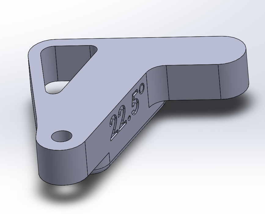
Okay here’s the thing. I have the solidworks part reliably re-building from 0 degrees to 45 degrees. This means I can feasibly make any angle I’d like without throwing any weird solidworks errors. I don’t want to manually enter the angle I want, and then revise the text for all of the infinity of angles that exist between 0 and 45 degrees. I also want to generate a pallet of blocks that step from 0 to 45 degrees in increments of 5 degrees. I ALSO want the text on the side of the block to update with the angle the block was set to so I don’t have to go in to every derived configuration and update the text.
Here’s how we do this (keep in mind I’m running SW14, so your mileage may vary).
- Make your part how you want it, and rename your “primary value” of your smart dimensions that you want to change to something meaningful eg: “set_angle@Sketch3”
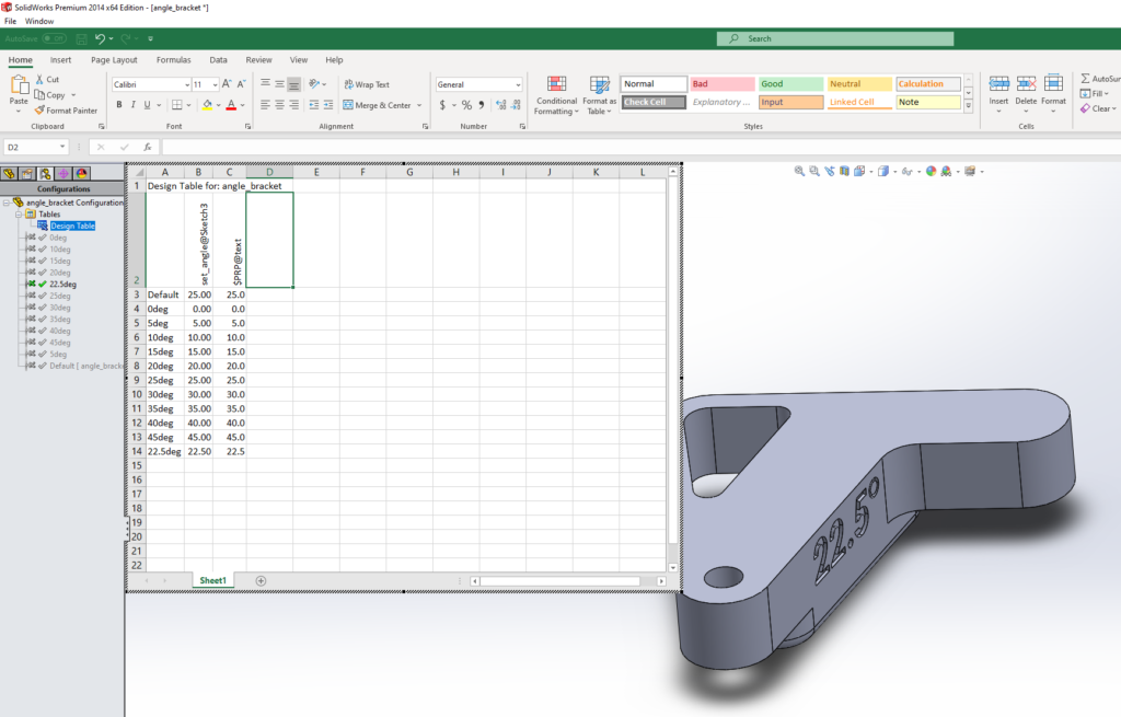
- File->Insert->Tables->Design Table…
- You should now be prompted with a list of primary values from your part. This is why you took the time to rename your primary value. Select “set_angle@Sketch3” and excel will automatically populate a new column with that name at the top and the value of that directly below.
- You can make as many new configurations as you’d like by adding another row. You will have to name them by entering the name in the column where “Defult” resides. I’d recommend something meaningful.
- This should successfully generate x number of spin-off parts with the values of smart dimensions changed appropriately.
- To get sketch text to update as a variable go to file->properties…->configuration specific
- Make a new property named “text”, type: text, value: 69420
- Go to your extruded cut or boss and edit the sketch text as so: $PRP:”text”
- Go back to your design table by right clicking on it and edit it. It should prompt you asking if you want to add the “text” property you just made.
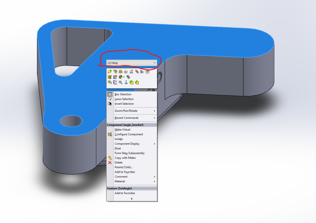
- Now your angles and text values reside as variables in an excel table!
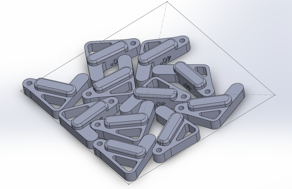
Use this to create as many variations as you want of your model. These derived configurations can then be loaded into an assembly with ease. This makes palleting up parts for 3D printing easy.
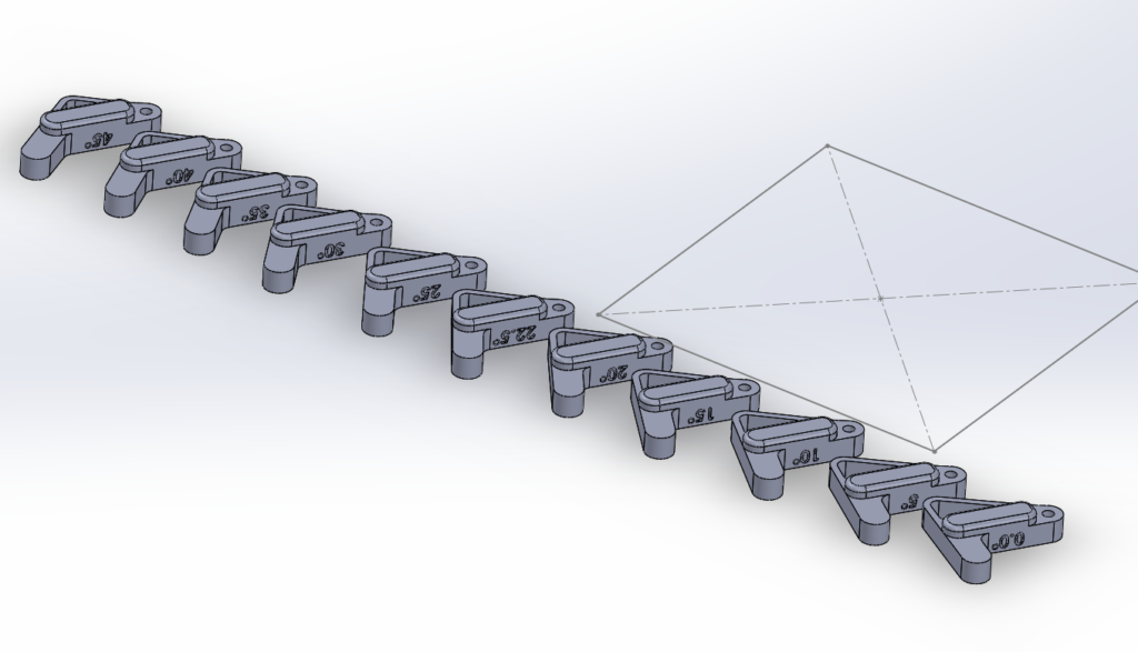
I inserted a sketch of my build plate are into my assembly as a guide for how many I can fit on to the build plate at once. From here you can generate an STL from the assembly as one part to save you hassle from having to get things stacked up in Cura or whatever.
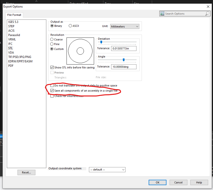
File->save as->.stl for the type->Options…->Check “Save all components of an assembly in a single file”
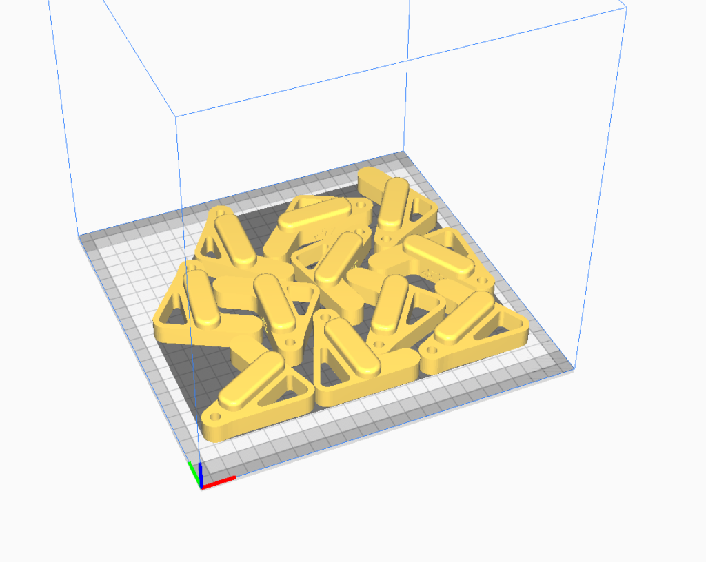
Import this STL into cura and now you have a pallet of different models you can print!

Here’s an angle block in the saw. Works like a charm!
Now don’t go expecting to get decimal-place-precision out of your chopsaw. But these guides work way better than the scale on the saw itself and can give you reproducible cuts if you need to adjust every time you cut.
Sources:
https://centralinnovation.com/technical-resources/learn/add-sketch-text-to-design-table/