Intro
I first heard of these displays when I saw a snipped of Adrian Black using them on Adrian’s Digital Basement in 2021. For only $20 per CRT it seemed like the perfect dumb project for me. Fast forward 4 years and I’ve done nothing with them. In fact I’ve had a kid, conceived another, and changed jobs since I bought these things. Time to put them to use. All my design files and code are available on my github.
Scope
At first I wanted to have a simple display…then I thought on it for a while…then I got goaded into a full audio-visual-tactile experience. Now I had a few objectives:
- Composite video output
- Speaker for music
- Display on/off control
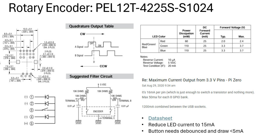
- Rotary encoder & button for volume/mute/power control
- LEDs (because they come with the encoder)
- USB -> Serial UART for console access without WiFi
Mechanical Design
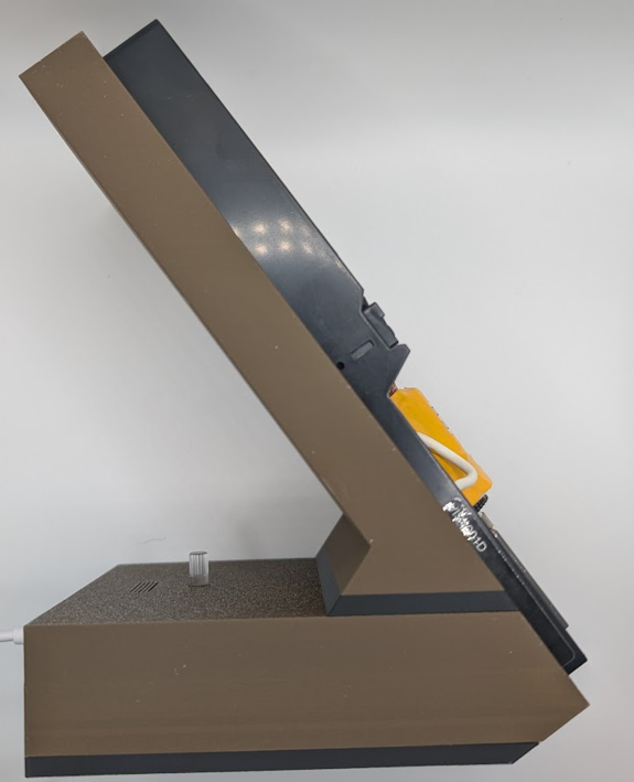
I really wanted to mimic some of the wood and plastic designs from the late 80’s early 90’s. I also knew I wanted heat-set inserts for easy modifications/improvements.
Initial prints were solely there to fit-check the CRT as my calipers don’t open wide enough to get an accurate height of the unit. Once the CRT fit the bezels I designed I was good to design the rest of the base.
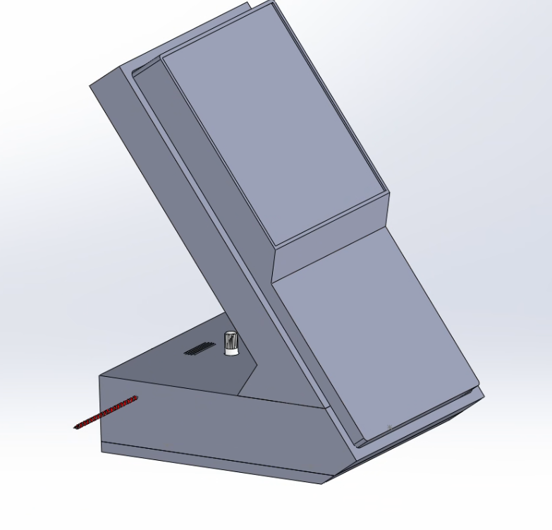
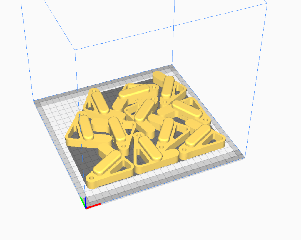
I’m pretty bad at enclosure design. But everything fit after a print or two….
With the existance of 0201 components and robots, I typically give my PCB a form factor before I place a single chip…or even put my design into schematic. The workflow goes as such:
- Define large-scale components (encoders, speakers, buttons, ports, etc)
- Import raspberry pi
- Mechanically position large scale components
- Check fit in the main assembly
- Fillet, add mounting holes, make pretty
- Export DXF
- Import into KiCad user.comments layer
- Layout board
- Export PCB as step
- Re-import into Solidworks (This step helps check the fit of other components like resistors or large inductors)
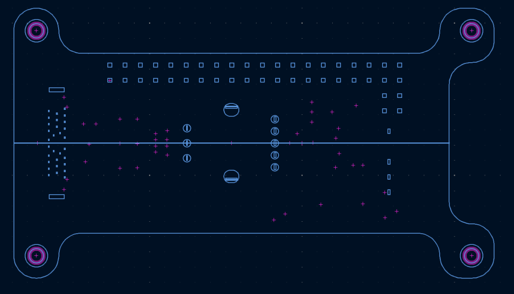
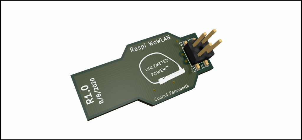
For my first rev of the PCB you can see a whole bunch of through-hole parts on the left side of the board. Initially I was going to go with a bulkhead-style USB C connector, however the part cost on that was like $30 and USB C connectors are sold for like $0.3 now. I digress.
To get the wood/plastic aesthetic, I used bambulab teak wood filament and matte black filament. In hindsight I probably would have used glossy black, but this was close enough.
Electrical Design
I decided to keep notes in powerpoint, because I can draw shapes and such. I think it was good diligence for a solo-design. Not sure if I would do it again in the future as it was quite tedious, but I had links and notes for every major component on the PCB. This is especially helpful when I needed example circuits and references.
I’m not sure why I had it in my head, but I did not want to give the CRT 12V boost power. I really wanted to USB PD to negotiate for the needed 12V.
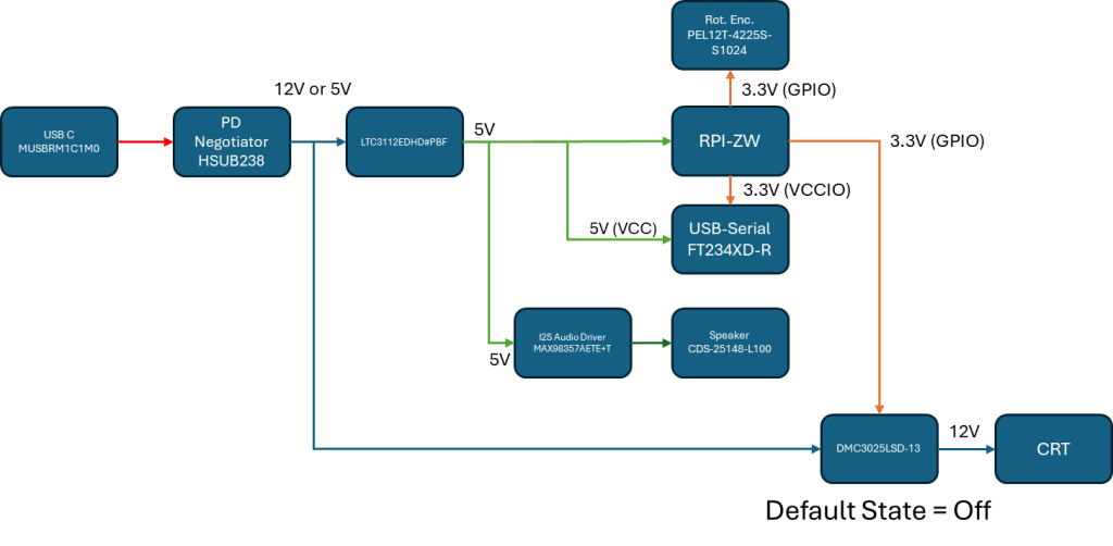
In hindsight it’s quite goofy to ask a buck converter to also pass-through voltage which is what I was planning on. Also, the USB PD chip I was using did not work. After this revision of the board, I decided it would be best just to provider 12V from the rail that can be supplied universally from all USB ports (power not guaranteed!)
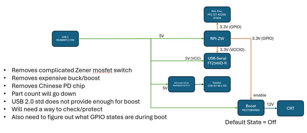
The new design was significantly more simple, but gives the user no protections if the port cannot supply the necessary 1A. Consider yourself warned.
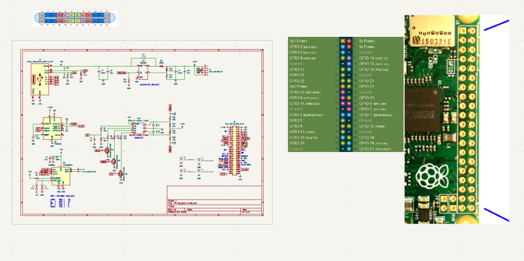
For the schematic I followed as simple of a layout as I could. I think it’s a relatively new thing to add pictures into KiCad but I leveraged that to make a quick and dirty pinout of the Pi and confirm USB C connections.
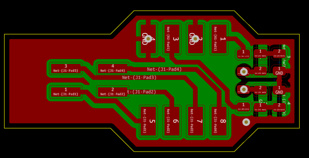
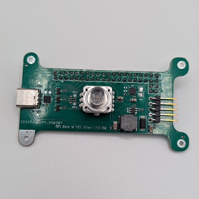
Layout of the PCB in this case was quite simple. I chose the cheapest trace/spacing specs offered by JLC PCB and went to work.
I was presented with no difficulties, until I tried to fit a bunch of 0805 components on to the PCB. This is where I reached the decision to drop down to 0402s and go with an assembly service.
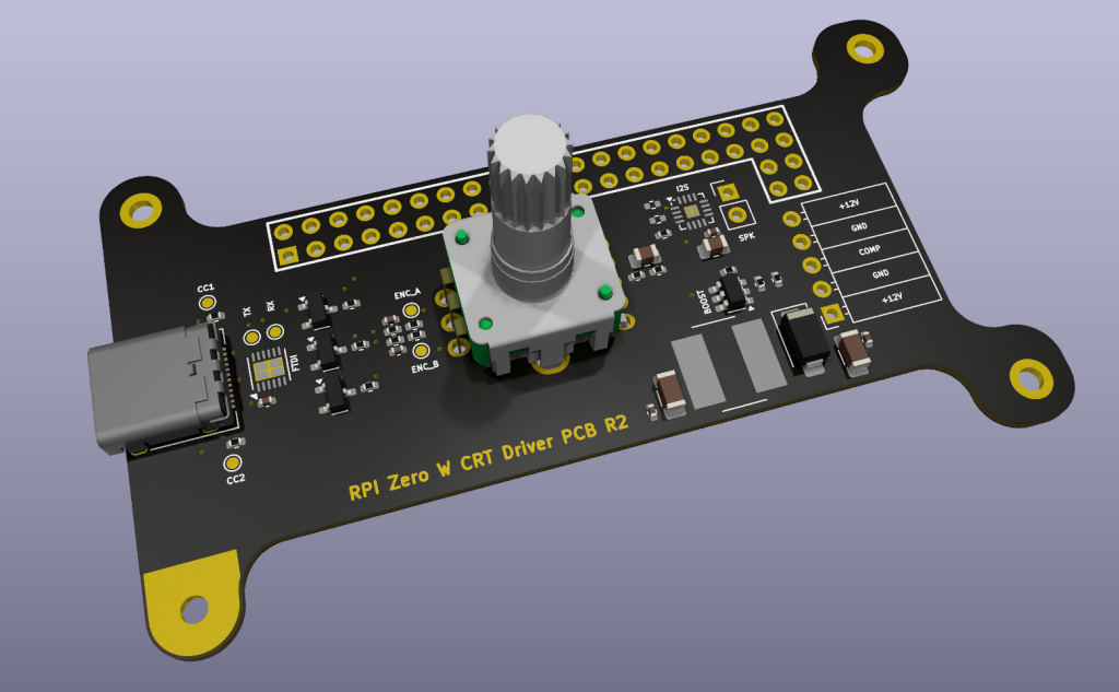
In principal I like to design my projects such that they can be easily reverse-engineered. This generally includes reference designators for all components in the silk screen, however I simply did not have the room on this board with the 0805s and really wanted to get the second revision out without focusing too much on silkscreen design.
One side thing I’m quite happy about was my poka yoke method of adding in the CRT connector (on the right side of the board). The connector can be installed either way and the CRT will still function as expected.
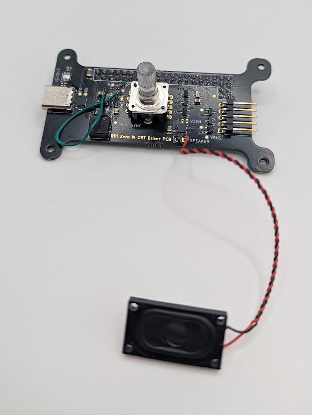
During extended testing I found out that I was overpowering the speaker and managed to burn one out. Luckily the I2S chip has short circuit protection and overtemp protection so the board was okay. I still need to figure out proper power settings for the speakers I bought.
Software
I started off with a project in visual studio. This allows me to prototype code much faster than a remote session on the pi. I also used relative directory positioning such that my code could be run on either system. For some reason I could not do remote development on my PI Zero W through VS Code. I was able to do this for a previous project, but that feature does not seem to be available anymore? Luckily, until I got PCBs in hand, I could write a majority of the code as system-agnostic besides GPIO stuffs. For GPIO development I turned to old-trusty WinSCP. Save the file in VSCode, drag and drop it on the pi, run it from the pi over SSH. Rinse and repeat.
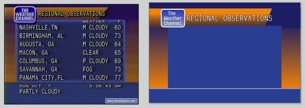
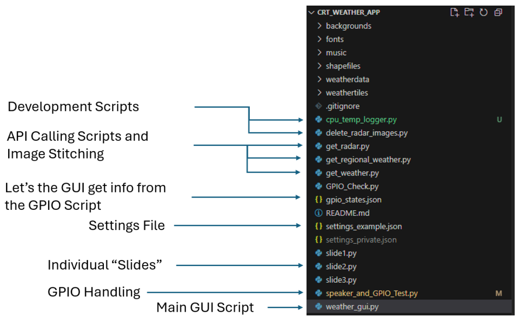
I’m pretty proud of how clever I was with the GUI. Instead of re-inventing the WeatherStar4000+ from scratch, I just copied it graphically, and added in dynamic elements only.
99% of this code was written with ChatGPT. As such, I wanted to make it as atomic as possible to avoid the bogging down that comes with excessively long sections of code. In my infinite free time I’ll come in and optimize things a bit
Side Bar: I had no idea that the WeatherStar4000+ Emulator existed. Knowing what I know now, I probably would have used that and just played the video from a webpage instead of re-inventing this from scratch.
The GPIO handling works well enough, but it would be nice to figure out how to get it to be more responsive. Right now I’ve got some really janky software PWM for the LED color control and weird debouncing going on. I probably should have written it as C code so it’s a bit less bloated.
I don’t play with VENVs in python so all libraries are imported as root “–break-system-packages”. Not the best thing to do, but this is dedicated hardware running a dedicated service. So, hell with it.
Another thing to note is the shapefiles come from NaturalEarth. The shapefiles are too large to host on Github so you’ll need to manually download them and add them to the “shapefiles” folder.
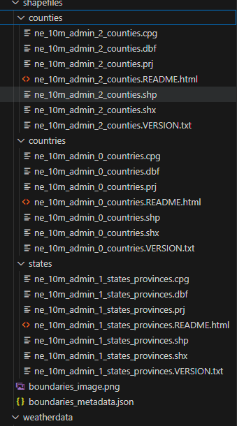
It’s been a while since I touched the code on this, but the get_radar.py script took forever to make, and I’m super proud I was able to get png weather data and accurately place it on a latitude-and-longitude grid, with boarders, then animate it. If anyone has any leads for free radar I would appreciate it. I was using NOAAs GOES satellite data, but it didn’t fit the aesthetic, and it also didn’t give good local data.
Closing Thoughts
It’s pretty, it’s goofy, it makes music, and gives me the weather for my friends and family.
Don’t turn up the volume too loud or you’ll melt the speaker (apparently).
I’m glad I got to get back out and do some small scale engineering again, even if it was for a hobby project. My current job has been more nut-and-bolt/simulation oriented and I missed the inconsequential nature of small hardware development.
I’m currently working on a youtube video version of this post for those audio-visual oriented. I’ll update this post when it’s published.
Acknowledgements
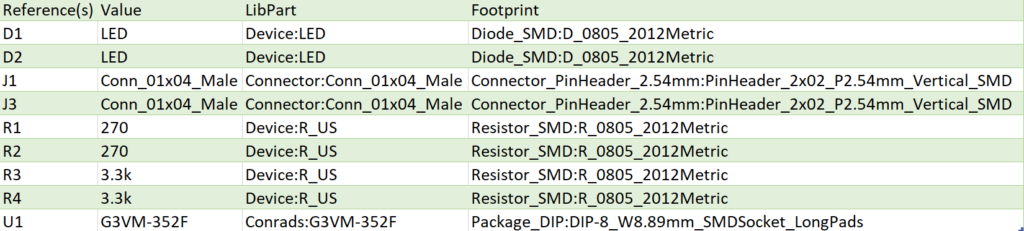
I’d like to thank the TWCClassics group for their Star JR font. Open weather map for the weather data. I would also like to thank Natural Earth data for their boundary shapefiles. This made the radar map much easier to implement. Tristan and Remington did a great job reviewing my PCB and caught some issues with R1 before I sent it out, so they earned a spot on my silkscreen.